Reactive Power Compensation in Enterprise Electrical Networks
Recently, due to increased production, the power consumption of electrical receivers used in primary and auxiliary processes has increased. This is occurring against a backdrop of steadily rising energy costs. Consequently, to reduce production costs, a rapid transition to energy-saving technologies and various methods for reducing electrical power and energy losses is necessary.
Depending on the type of equipment used, the load in electrical networks is divided into active and reactive (inductive and capacitive). Consequently, both active and reactive energy is consumed from the electrical network.
Active energy is converted into useful energy — mechanical, thermal, etc. — while reactive energy is not associated with useful work and is spent on generating electromagnetic fields in asynchronous electric motors, transformers, induction furnaces, welding transformers, chokes, and lighting fixtures. A measure of reactive power consumption is the power factor (PF), which shows the ratio of active power P to apparent power S consumed by an electrical load from the grid:
PF = P / S
Optimally, this value should approach unity and comply with regulatory requirements.
Reactive power consumption leads to negative effects such as additional losses in conductors due to increased current, over-rated transformers and cables, deviations in grid voltage from the nominal value, and overloading of the transmission grid.
Significant reactive power consumption leads to reduced voltage levels, which is extremely unfavorable for electric motor operation due to reduced torque.
Reactive current places additional stress on transmission lines, leading to increased wire and cable cross-sections and, consequently, increased capital expenditures on external and on-site grids. Reactive power, along with active power, is accounted for by the electricity supplier and, therefore, is subject to payment at current tariffs, thus constituting a significant portion of the electricity bill. The cheapest and most effective way to improve the performance of electrical systems is reactive power compensation.
The most common method of reactive power compensation in industrial power grids is the use of capacitor banks.
To achieve optimal power factor, automatic banks are most effective. They connect the required number of capacitors depending on the network's reactive load, with capacitor activation controlled by a microprocessor.
Automatic capacitor banks ensure an average daily power factor of at least 0.97; they eliminate the generation of reactive energy into the grid during off-peak hours and provide information on the parameters and condition of the electrical grid.
This not only increases the power factor (PF) to the required value and reduces energy losses in power grid elements, but also serves, among other measures, as a means of regulating voltage at various points in the grid and improving power quality.
For many enterprises, due to limited transmission capacity and increased active power losses in the distribution network, the use of automatic capacitor banks is essential.
When designing reactive power compensation systems, it is important to consider the nature of load changes in the enterprise's electrical networks.
If the enterprise's power system is characterized by significant fluctuations in reactive power, it is advisable to use capacitor banks with automatic power regulation.
In those sections of the power system where reactive loads are present in the network almost constantly, it is possible to install unregulated, continuously operating capacitor banks, which are significantly less expensive than equipment with automatic power regulation.
An optimal solution in terms of cost and efficiency is achieved by combining unregulated and automatic capacitor banks, which are placed in sections of the electrical network with the appropriate reactive power regime.
Based on the connection point, the following compensation schemes are distinguished:
With centralized compensation, the capacitor bank is connected to the transformer substation. As a result, the 6-10 kV networks and substation transformers are relieved of reactive power, while the in-plant distribution networks remain unloaded.
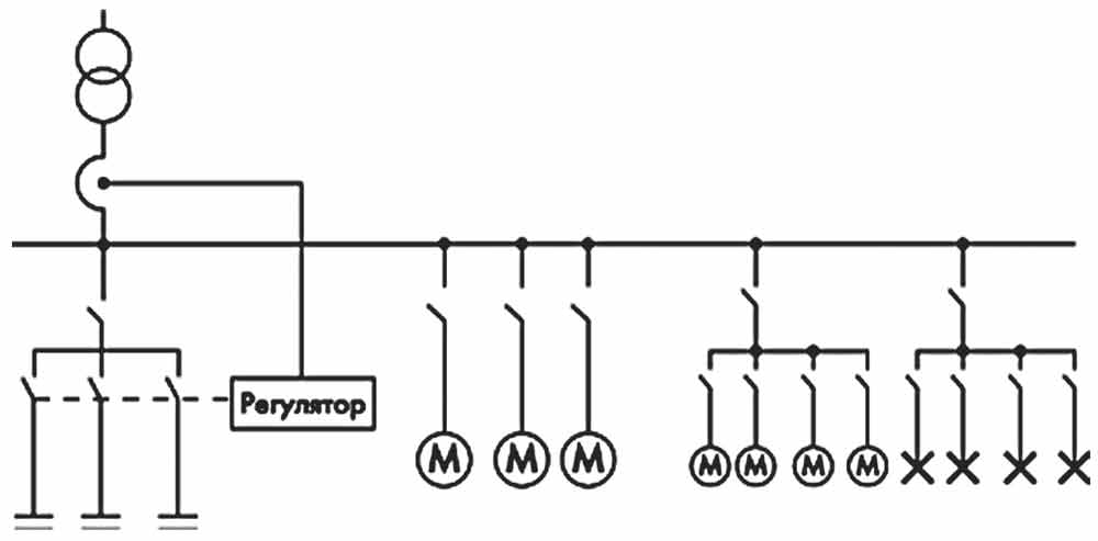
Fig. 1. Centralized Compensation
Centralized Compensation
With group compensation, capacitor banks are located in workshops. This also relieves the in-plant networks, but the distribution networks of individual power consumers may remain unloaded.
Group Compensation
With individual compensation, the capacitor bank is connected directly to the terminals of the power consumer.
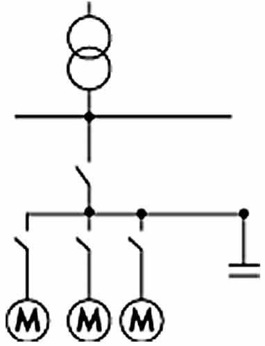
Fig. 2. Group compensation
This connection is the most efficient due to the complete compensation of the reactive power of the distributed network of the power consumer during operation, but it is also the most expensive method, since the capacitors are not used during the power consumer's downtime.
Another advantage of individual compensation is that the capacitors use the same switching device as the power consumer, and the power consumer serves as the discharge resistor. This greatly simplifies both the reactive power compensation device itself and its maintenance.
Individual Compensation
The cost of the solution can also be reduced without sacrificing quality through a flexible combination of centralized, group, and individual compensation methods.
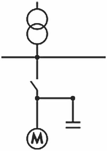
Fig. 3. Individual compensation
By type of regulator, compensation systems are divided into:
• conventional (relay) - in which capacitor switching is performed using electromechanical relays;
• static (thyristor) - in which thyristor switches are used.
In static installations, capacitor switching occurs at zero voltage, which offers the following advantages over conventional installations:
• High response speed - up to 14 switching operations per second instead of one every 5-20 seconds;
• Low noise levels due to the absence of current surges during switching;
• Low capacitor wear for the same reason;
• High reliability of key equipment due to the absence of mechanical parts;
• Reduced losses due to the absence of discharge resistors.
When selecting an installation, the following characteristics are determined:
• Installation type - conventional or static;
• Power - the maximum reactive power that can be compensated;
• Compensation step (stage) - the minimum increment by which the capacitance of the connected capacitors changes;
• The need for harmonic filtering.
Implementation of an automated reactive power compensation system will allow:
• Reduction in electricity costs by 3-5%;
• Reduction in reactive power consumption;
• Reduction in distribution network operating costs;
• Minimize active power and energy losses in power grid elements;
• Increase the power factor to the required value;
• Transmit higher power through the existing cable network.
• Optimize the operating mode of electrical grids;
• Eliminate the generation of reactive energy into the grid during off-peak hours;
• Reduce the load on feeder transmission lines, transformers, and distribution networks;
• Provide information on the parameters and condition of the electrical grid;
• Provide automatic monitoring of changes in reactive power and other grid parameters.
On average, the system pays for itself within 8-18 months.
Leonid Zilbergleit, Technical Director
Anton Gavrilov, Marketing Manager
***