Electronics and Microelectronics
SIEMENS – Temperature-Dependent Protection Devices
The prerequisite for good motor protection is the selection of the correct sensor, its proper installation in the motor winding, and the use of a suitable trip unit.
The sensing element determines the type of trip unit.
Thermal sensors are semiconductor resistors that change their resistance depending on temperature. A distinction is made between thermistors with a positive and negative temperature coefficient (PTC) (Fig. 1).
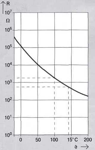
Fig. 1. Resistance characteristics of thermal relays operating on the principle of bimetallic strip deformation
Positive Temperature Coefficient (PTC) Thermistors
Positive temperature coefficient (PTC) thermistors, also known as PTCs, are most often used for temperature-dependent protection of AC motors. These PTCs are characterized by a sharp increase in resistance over the rated trip temperature range (Fig. 2). This sudden change in resistance is converted in the associated trip unit (e.g., 3UN21) into a command that is used to trip the motor. The nominal response temperature of the sensor depends on the motor insulation class. PTC thermistors are primarily installed in serially produced motors, for which the permissible temperature limits and precise thermal characteristics are determined prior to motor manufacture.
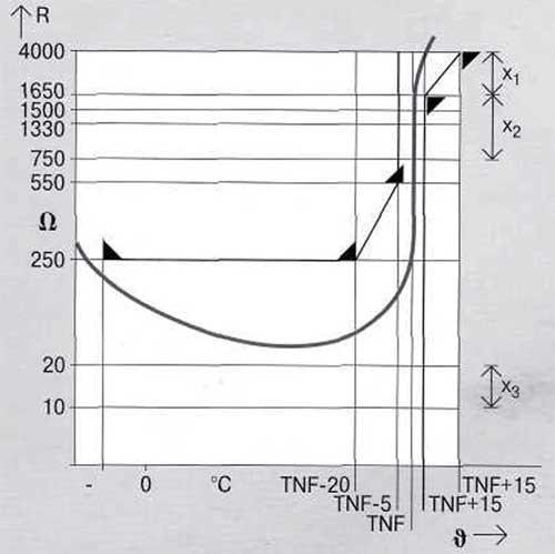
Fig. 2. TNF nominal response temperature. X1 is the VDE response range (3UN2 tripping units: from 2800 to 3000 W). X2 is the VDE tripping range (3UN2 tripping units: from 1650 to 1500 W). X3 is the tripping range for detecting a short circuit in the temperature sensor circuit.
Bimetallic Sensors
Along with semiconductor resistors, which change their resistance depending on temperature, so-called bimetallic sensors are used for simpler applications. They open and close a contact at a preset response temperature. These bimetallic switches, like semiconductor sensors, are installed in the stator windings. Although they are not as accurate, they can be used with thermistor tripping devices without short-circuit detection in the sensing circuit.
KTY Sensors
These semiconductor temperature sensors have a rising temperature characteristic without a step-up function. They allow winding temperature measurement.
They are primarily found in variable speed drives. KTY sensors are connected to the inputs of frequency converters.
Installing PTC Thermistors
PTC thermistors are installed in the stator winding.
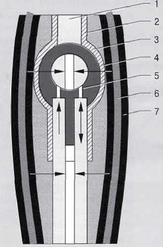
Fig. 3. Cross-section of thermistor and winding of an AC motor. 1 – Thermistor, 2 – Solder joints, 3 – Thermistor insulation, 4 – Winding insulation, 5 – Connecting wires, 6 – Winding wire, 7 – Wire insulation
Figure 3 shows a cross-section of a single thermistor embedded in the winding. To ensure good heat transfer, it is important to correctly position the sensor in the winding. This will ensure that, as the winding temperature rises, the sensor's rated response temperature is reached within a sufficiently short time before the motor enters a critical state.
This applies primarily to operating conditions such as heavy motor acceleration with acceleration times exceeding 10 seconds, single-phase operation, current asymmetry, motor blocking, cooling failure, intermittent operation, and high switching frequency in variable speed drives. Typically, temperature sensors in the motor are connected in series and routed to the motor terminal block. The number of PTC thermistors connected in series is determined by the total cold resistance of all connected thermistors. For example, for 3UN2 tripping units, this is <1.5k Ohms. Type A Trip Units and Sensors
A prerequisite for effective temperature-dependent motor protection is the definition of appropriate interface data between PTC thermistors and trip units. Therefore, the general requirements and application options for temperature sensors and trip units are outlined in DIN VDE 0660, Part 302/02.87 (IEC 34-11-2, Section 1). The parameters for the interaction of PTC thermistors and trip units are specified in DIN VDE 0660, Part 302/02.87 (IEC 34-11-2, Section 2). According to these standards, PTC thermistors must have a resistance-temperature characteristic curve corresponding to Figure 2 regarding the rated trip temperature.
To ensure normal motor operation, the following operating conditions are established for tripping devices if a variable resistance is detected at the temperature sensor connection point:
• They must switch on and off at a resistance value of <750 ohms.
• They must switch off when the resistance increases, if the resistance value is between 1650 and 4000 ohms (see Fig. 2).
• They must switch on and off when the resistance in the sensor circuit decreases from 1650 to 750 ohms (see Fig. 2).
• When connecting a 4000 ohm resistor and operating the tripping device at rated voltage, the voltage of the connected sensor must not exceed 7.5 V.
• When connecting a capacitance of up to 0.2 μE, there must be no noticeable change in the operating values of the tripping device.
If these criteria are met for PTC thermistors and the corresponding tripping devices, they can be classified as type "A" in accordance with DIN VDE 0660. Parameterization allows the user to independently replace tripping units for motors protected by PTC thermistors.
3UN2 Thermistor Trip Unit
The 3UN21 thermistor trip units with a 22.5 mm mounting width, the 3UN22 for 2 thermistors, or the 3UN26 for 6 thermistors with a 45 mm mounting width, provide the user with a highly compact control system. Connection markings according to DIN EN 50005, wiring diagrams printed on the front of the unit, and easy access to the screw terminals facilitate handling during installation and maintenance. The monitoring scope of the thermistor circuit or the tripping characteristic after tripping can be defined already during the design stage by selecting the appropriate reset function (Fig. 4). In addition, these units are available with various auxiliary contacts (1 changeover contact, 1 normally open + 1 normally closed contact, and 2 changeover contacts). In the event of a control voltage failure, the various characteristics of the tripping units must be taken into account. 3UN2 tripping units operate with both type A thermistors according to DIN VDE 0660, Part 303, and with thermistors according to DIN 44080/44081/44082.
When connecting more than three thermistors in series, this is necessary, for example, when protecting a pole-changeover motor with two separate windings; proper operation of the circuit is guaranteed down to a total cold resistance of 1.5Ω.
Integrated interference protection and thermistor circuit monitoring improve motor reliability.
When using thermistor tripping units, sensor wires often run in close proximity to high-current wires. This sometimes leads to situations where inductive or capacitive pickups cause interference in the measuring circuit. The sensor protection circuit in the 3UN2 tripping unit suppresses such interference signals, eliminating the need for expensive shielding for the thermistor wires.
Testing of the interference protection circuit complies with the requirements of IEC 801 "Electromagnetic compatibility of measuring, control, and regulating equipment in industrial engineering, parts 1-4." For example, testing under conditions of fast, continuously occurring interference pulses over a specified time interval shows that the tripping units meet severity criterion 4. This corresponds to immunity to interference of up to 4 kV for supply wires and up to 2 kV for signal and control wires. All tripping units operate on the quiescent current principle and self-monitor for open circuits in the thermistor circuit. The 3UN2131 tripping units are equipped with a short-circuit detection circuit (KSE) in the thermistor circuit. This circuit trips the motor when the resistance in the thermistor circuit drops below 20 ohms. This detects a short circuit, for example, in a thermistor wire.
Tripping Unit Performance During Supply Voltage Failures
Control voltage dips, which may occur in the switchgear during short-circuit tripping or when large motors and transformers are switched on, do not affect tripping. False tripping can be prevented by the protection function against short-term voltage interruptions of up to 200 ms.
For longer control voltage dips, the tripping unit may have different characteristics depending on the version. A distinction is made between:
• tripping devices that, if the control voltage is lost for more than 200 ms, switch to the "off" position and, when voltage is restored, return to their original state, as before the control voltage was lost. These devices are used in switchgear where there is no control voltage monitoring, and
• tripping devices that do not change their state when the control voltage is lost. Only in the event of a motor thermal overload due to a wire break or short circuit in the thermistor circuit, with the control voltage present, does the auxiliary contacts change state. These devices are used where the control voltage is separately monitored.
In tripping devices with manual reset, the "off" state is remembered. When the control voltage is lost, the tripped state is retained. Only after the motor has cooled down does the device reset by pressing the Test/Reset button on the device or by using the "remote reset" circuit in the 3UN2131, 3UN22, and 3UN26 trip units (see Fig. 4), for example, from the main control panel. By shorting the remote reset contacts with a jumper, this process occurs automatically after the motor winding has cooled.
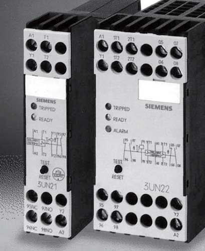
Fig. 4. 3UN2 Thermistor Motor Protection Devices
Use of Thermistor Trips
Thermistor motor protection devices are primarily used where current-dependent overload relays cannot provide protection. In such cases, this device serves as the sole motor protection device, or in particularly critical applications, it is used in conjunction with an overload relay. Thermistor tripping devices primarily provide motor overload protection in the following situations:
• during continuous and intermittent operation
• during heavy acceleration
• at high switching frequencies
• during single-phase operation and current asymmetry, and
• insufficient cooling.
However, short-circuit protection of motors must be ensured by installing fuses or circuit breakers.
Motors with Critical Stators and Rotors
The required protection using thermistor tripping devices depends on which part of the motor is more vulnerable — the stator or the rotor. In AC motors with a critical stator, such as Siemens 1LA5 motors with a power range of up to 15 kW, the permissible maximum temperature of the stator winding in a blocked state increases faster than that of the rotor. Since the temperature increase is promptly detected by temperature sensors integrated into the stator, this ensures that the rotor does not overheat. In this case, a thermistor trip unit is sufficient to provide complete thermal protection for the motor.
High-power motors are generally vulnerable on the rotor side. In this case, a locked rotor reaches the maximum temperature faster than the stator, while the temperature sensors integrated into the stator reach the rated trip temperature TNF with a delay.
Additionally using a three-pole overload relay or a 3RB12 motor protection relay improves protection, especially when starting with a locked rotor from a cold state. The overload relay is set to the rated motor current and also protects the motor connection wires.
Protection of Explosion-Proof Motors
Motors with the "Increased Explosion Safety" EEx e protection class must be certified by the Physikalisch-Technische Bundesanstalt (PTB). If protective functions are to be implemented using positive temperature coefficient (PTC) thermistors, the motors, including the thermistors, must undergo type testing according to VDE 0171 and receive a certificate. For this purpose, the PTB has developed a test protocol for a specific motor type. This protocol regulates the testing of PTC thermistors and tripping devices.
In addition to motors, the PTB also tests thermistor tripping devices and temperature sensors. Afterward, the tripping devices receive a uniform inspection mark. 3UN2 tripping devices for AC motor protection are certified by the PTB.
If positive temperature coefficient thermistors and tripping devices are used with a motor certified by the RTB Institute, a test report for the overload relay is not required. Separate requirements for mechanisms in DIN VDE 0165, Section 6.1.4, should be observed. However, if the test report specifies that thermally delayed overload relays with phase failure sensors are used for motor protection, additional thermistor tripping devices may be used without the RTB certification mark.
***